


 152 / 218

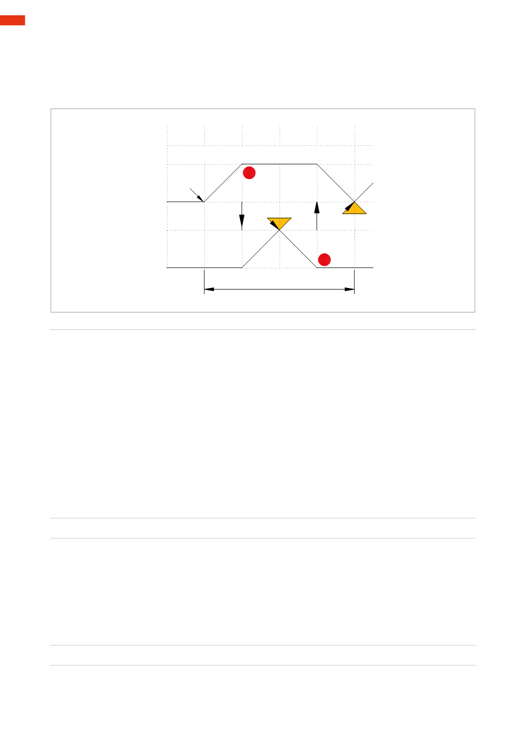
Figure 37
Existing relationship between
movements
and
signals
:
toobtain the stroke
A+
theoutput signals from
I.C.
and
a0
are required
to obtain the stroke
B+
the output signal from
a1
is required
to obtain the stroke
B –
the output signal from
b1
is required
to obtain the stroke
A –
the output signal from
b0
is required.
_
A
+
B
_
I.C.
+
a1
1
b1
b0
a0
2
3
4
1
cycle
Fig. 37
Principles of logic
In any pneumatic automation, in addition to defining the sequence, it is necessary to implement all of the
information required for its execution. To demonstrate we examine an automated sequence designed to separate
bars for a subsequent selection. Schematic representation of the sequence:
Figure 38
Pos. 1
: information “
a
” indicates whether the separator has loaded the bar.
Pos. 2
: information “
b
” verifies that there are bars present in the stock.
Pos. 3
: information “
c
” indicates that the discharge zone is free.
Pos. 4
: mathematical logic is based on the two states
TRUE
or
FALSE
, with a numerical value assigned to each
respectively:
TRUE
=
1
FALSE
=
0
We apply this logic to our example
Information “
a
” Has the separator loaded a bar?
TRUE
a
=
1
Information “
b
”
Are there bars present in the stock?
TRUE
b
=
1
Information “
c
”
Is the discharge zone free?
TRUE
c
=
1
This information combined together and processed, should result in command
X
as an output. In this case, as all
pieces of informationmust be TRUE themathematical rule and its result are:
X= a * b * c
X=1
In this condition it is possible to have command
X
that enables themovement of the automatic sequence.
Pos. 5
: One bar descends the rail.
5
150
CAMOZZI
>
CIRCUIT TECHNIQUE