


 149 / 218

CIRCUIT TECHNIQUE
+
_B
3
A_
+
2 1
4
last impulse
received
last impulse
received
A
B
P
A
P
B
Fig. 27
Figure 28
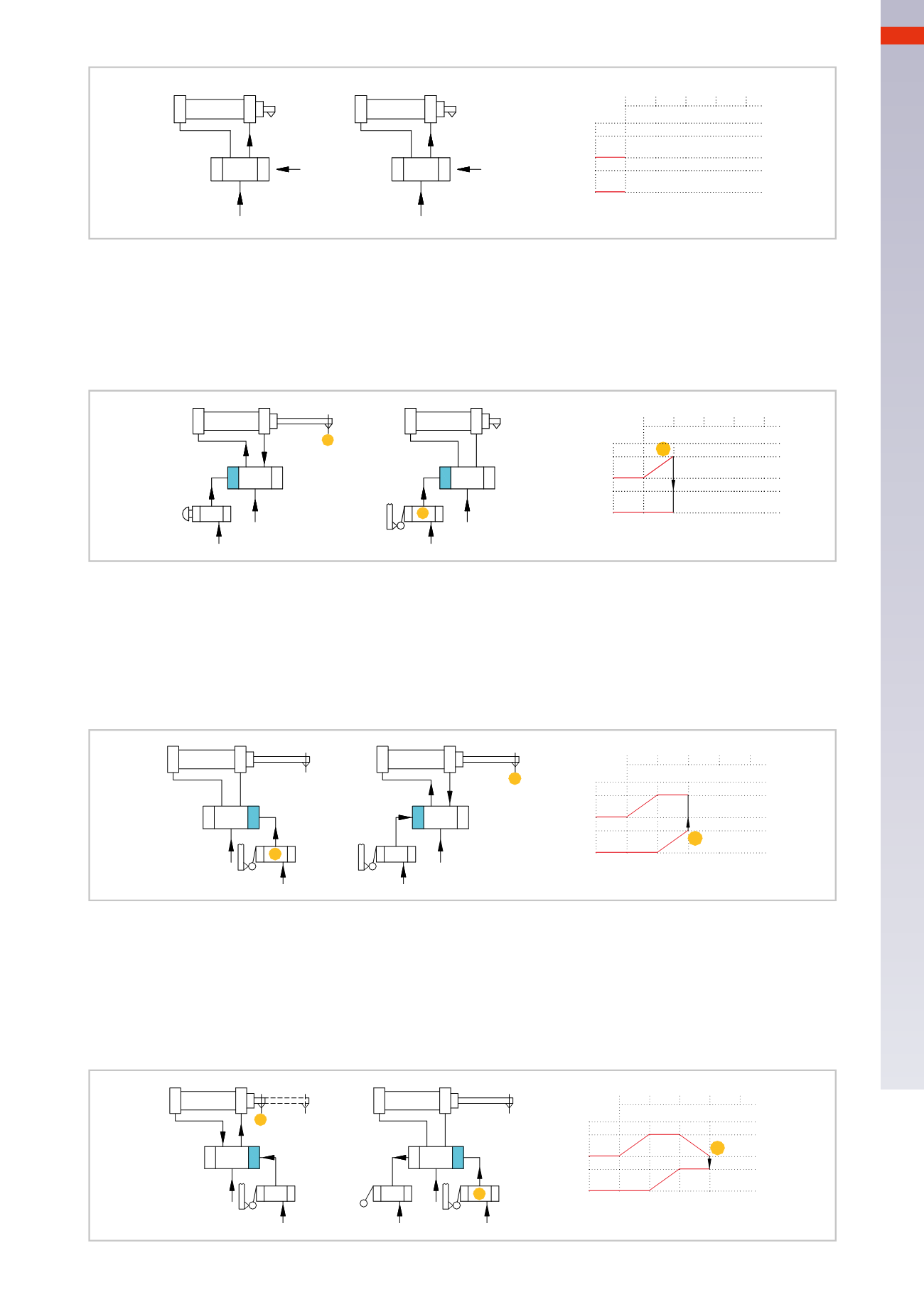
Phase1
: by using a pilot valvewith a pushbutton, the actuating device on the left side of the valve
P
A
is operated,
which switches and feeds the rear chamber of cylinder
A
. Its piston rod/pistonmoves and advances to the positive
end position actuating the limit switch
a1
.
Note
: Observe that in the flow diagram, the output signal from the limit switch
a1
enables the movement of the
piston rod/piston of the cylinder
B
.
+
_B
1
A_
+
a1
2 3 4
a1
a1
A
B
P
A
P
B
Fig. 28
P
A
A
a1
P
B
a1
B
b1
b1
3
B_
_A
+
+
a1
2 1
4
b1
Fig. 29
Figure 29
Phase2
: thepiston rod/pistonof cylinder
A
remains stationary, the signal generatedby the limit switch
a1
operates
the actuating device on the left side of the valve
P
B
which, by changing over, feeds the rear chamber of cylinder
B
.
Its piston rod/piston reaches the positive end position, activating the limit switch
b1
.
Note
: observe in the flow diagram, the output signal from the limit switch
b1
enables themovement of the piston
rod/piston of cylinder
A
. During the stroke of cylinder
B
, the limit switch
a1
remains activated as the piston rod/
piston of the cylinder
A
is stationary in the positive end position.
Figure 30
Phase 3
: the signal generated by the limit switch
b1
operates the actuating device on the right side of the valve
P
A
, which, through its changeover, feeds the front chamber of cylinder
A
. Its piston rod/piston moves, releasing
limit switch
a1
and reaching the end position, thus activating the negative limit switch
a0
.
Note
: observe that in the flow diagram, the output signal from the limit switch
a0
enables the movement of the
piston rod/piston of cylinder
B
. During the stroke of cylinder
A
, the limit switch
b1
remains activated, as the piston
rod/piston of cylinder
B
is stationary at the positive end position.
B
P
A
b1
a1
a0
A
B
b1
a1
_
1
A_
+
+
a1
2 3
P
B
b1
4
a0
a0
Fig. 30
5
147
CAMOZZI
>
CIRCUIT TECHNIQUE