


 155 / 218

CIRCUIT TECHNIQUE
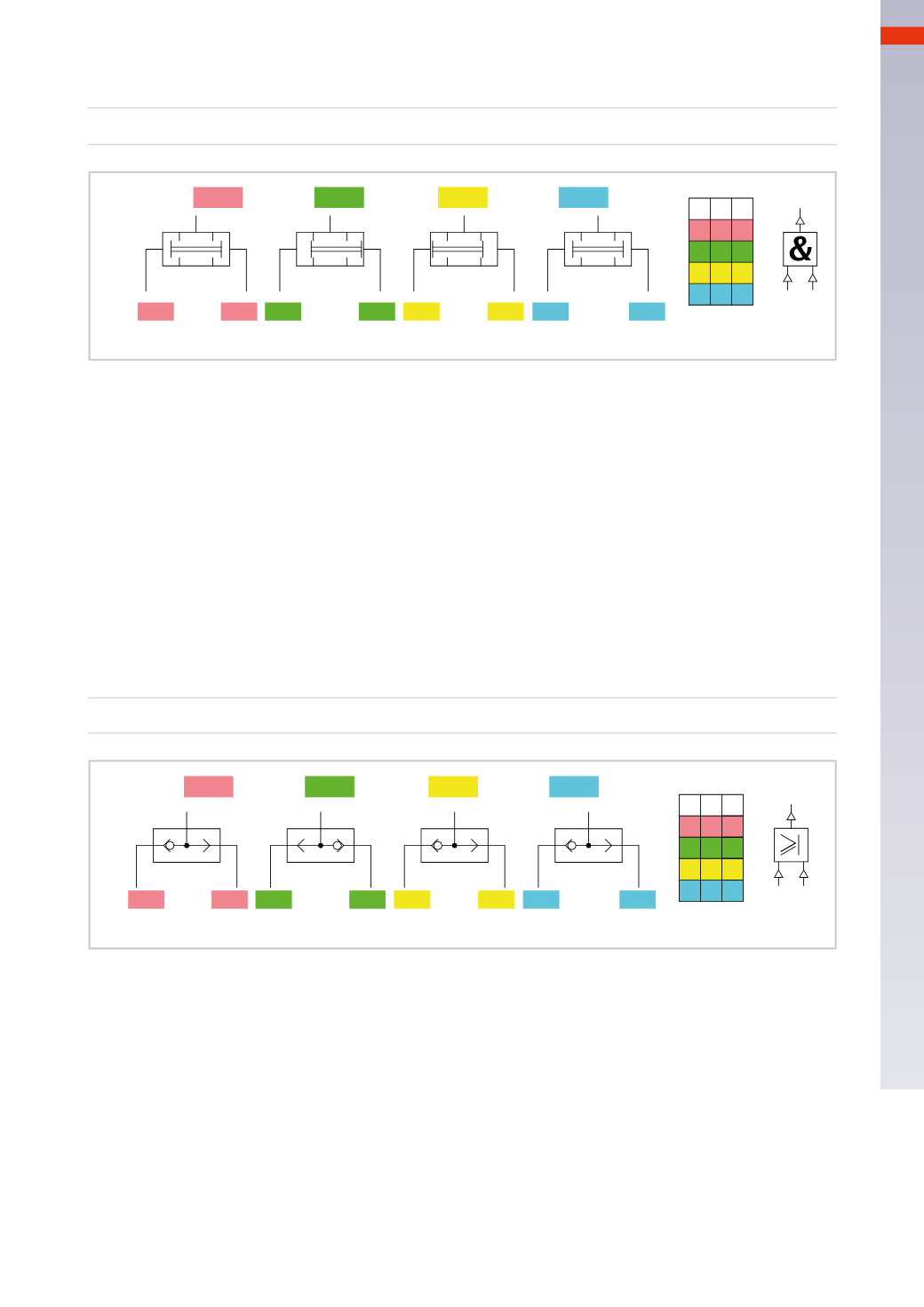
The product of the status of the two variables “
a
” and “
b
” determines the status of output
X
.
X= a * b
a b X
0 0 0
1 00
1 0 0
1 1 1
X
a b
X=0
X=0
X= 0
X= 1
a= 0
a=0
a=1
a=1
b=0
b=0
b=1
b=1
Fig. 41
Figure 42
OR
function
This valve gives an output signal if at least one of the two pilot signals is present.
There is an output signal
X
only if “
a
” or “
b
” are
TRUE
(they are present).
The presence of two pilot signals, whereby each may have two states, brings the total possible combinations to
four, in three of these combinations the variable
X
has status
1
.
If
a
=
0
and
b
=
0
then
X
=
0
; there are no signals present
If
a
=
1
and
b
=
0
then
X
=
1
; the input signal from “
a
” pushes the sphere towards “
b
”
closing the passage towards
X
If
a
=
0
and
b
=
1
then
X
=
1
; the input signal from “
b
” pushes the sphere towards “
a
”
closing the passage towards
X
If
a
=
1
and
b
=
1
then
X
=
1
; if the pressures are equal, the first received signal passes,
if the pressures are different the signal with the higher pressure passes through.
The sum of the two variables “
a
” and “
b
” determine the status of
X
.
X= a+ b
a b X
0 0 0
1 10
1 1 0
1 1 1
X
a b
X= 0
X=1
X= 1
X= 1
a= 0
a= 0
a=1
a= 1
b=0
b=0
b=1
b=1
Fig. 42
An example of the application of basic logic functions
We use the previously analysed bar handling plant as our example, describing its operation according to the
principles of logic.
The initial conditions required are:
IF
the separator has loaded the bar, information “
a
”
AND
there are other bars in the stock, information “
b
”
AND
there are
NOT
bars located on the discharge zone, information “
c
”
THEN
it is possible to control the cylinder from a certain position, information “
d
”
or from another position, information “
e
”
5
153
CAMOZZI
>
CIRCUIT TECHNIQUE