


 178 / 218

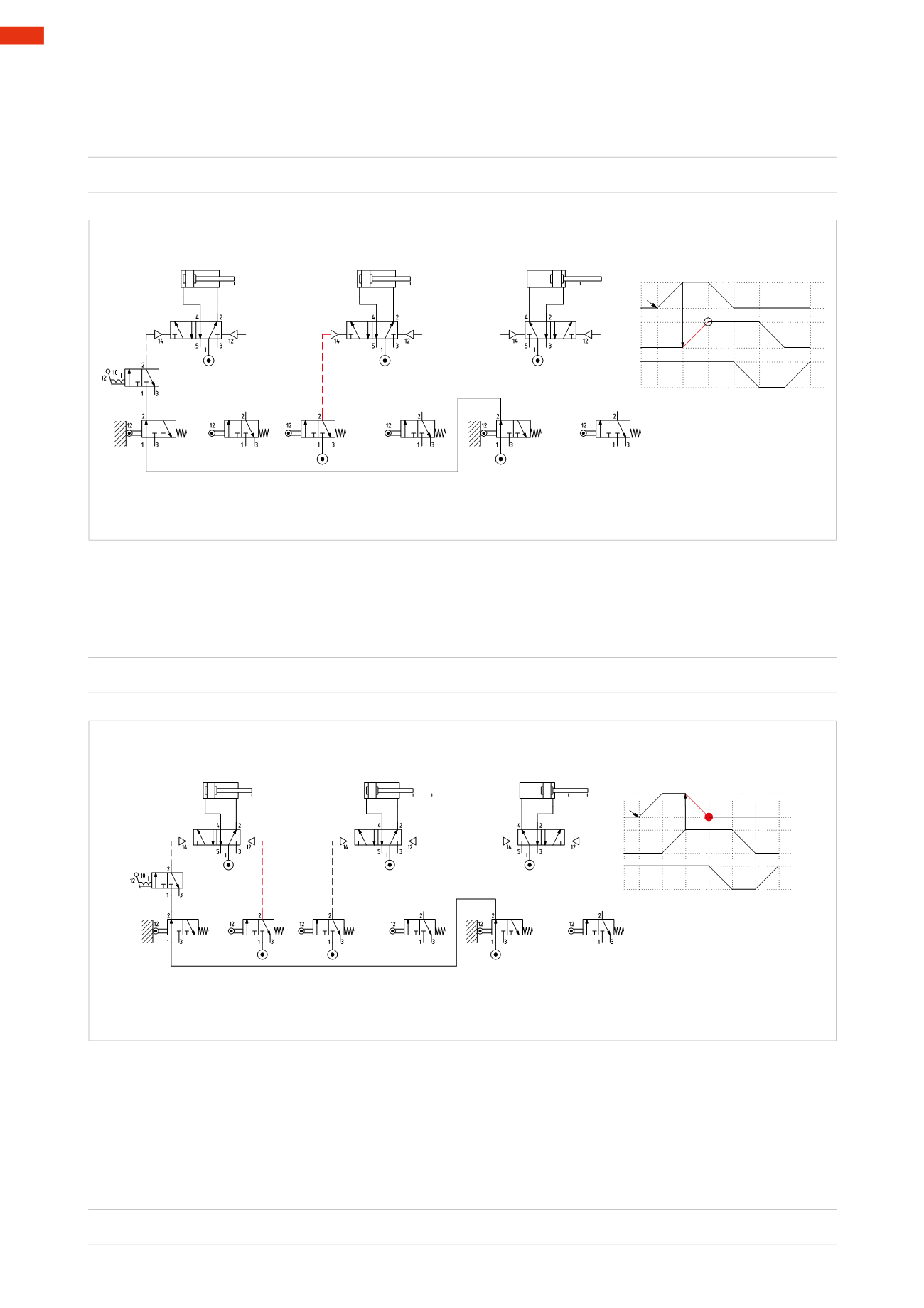
Figure 80
Phase 3
:
A –
The limit switch
b1
, which enables the negative stroke of the piston rod/piston of cylinder
A
, can be fed from the
compressedair networkas thepositive strokeonlyoccurs in the subsequent cyclewhen limit switch
b1
isnot active.
A –
=
b1
A+=b0 * c1 * I.C.
B+=a1
A - = b1
B
C
+
-
5
A
1 2
a1
4
6 1
3
+
-
+
-
b1
a0
c1
b1
a1
b0
a0 a1
b0 b1
c0 c1
A
B
C
I.C.
I.C.
Fig. 80
Figure 79
Phase 2
:
B+
Limit switch
a1
, which determines the start of cylinder
B
, can be fed from the compressed air network as its
operation ends after Phase 3.
B+
=
a1
A+=b0 * c1 * I.C.
B+=a1
B
C
+
-
A
+
-
+
-
b1
c1
a1
b0
a0 a1
b0 b1
c0 c1
A
B
C
I.C.
I.C.
5 4
6 1
3
1
2
Fig. 79
Figure 81
Phase 4
:
C –
The limit switch
a0
, which enables the negative stroke of the piston rod/piston of cylinder
C
, can be fed by the
output of limit switch
b1
as:
• the air supply coming from
b1
is present prior to the activation of
a0
.
• limit switch
a0
does not present itself for a second time during the sequence.
• limit switch
b1
is no longer active in the presence of
C+
.
C –
=
b1 * a0
5
176
CAMOZZI
>
CIRCUIT TECHNIQUE