


 179 / 218

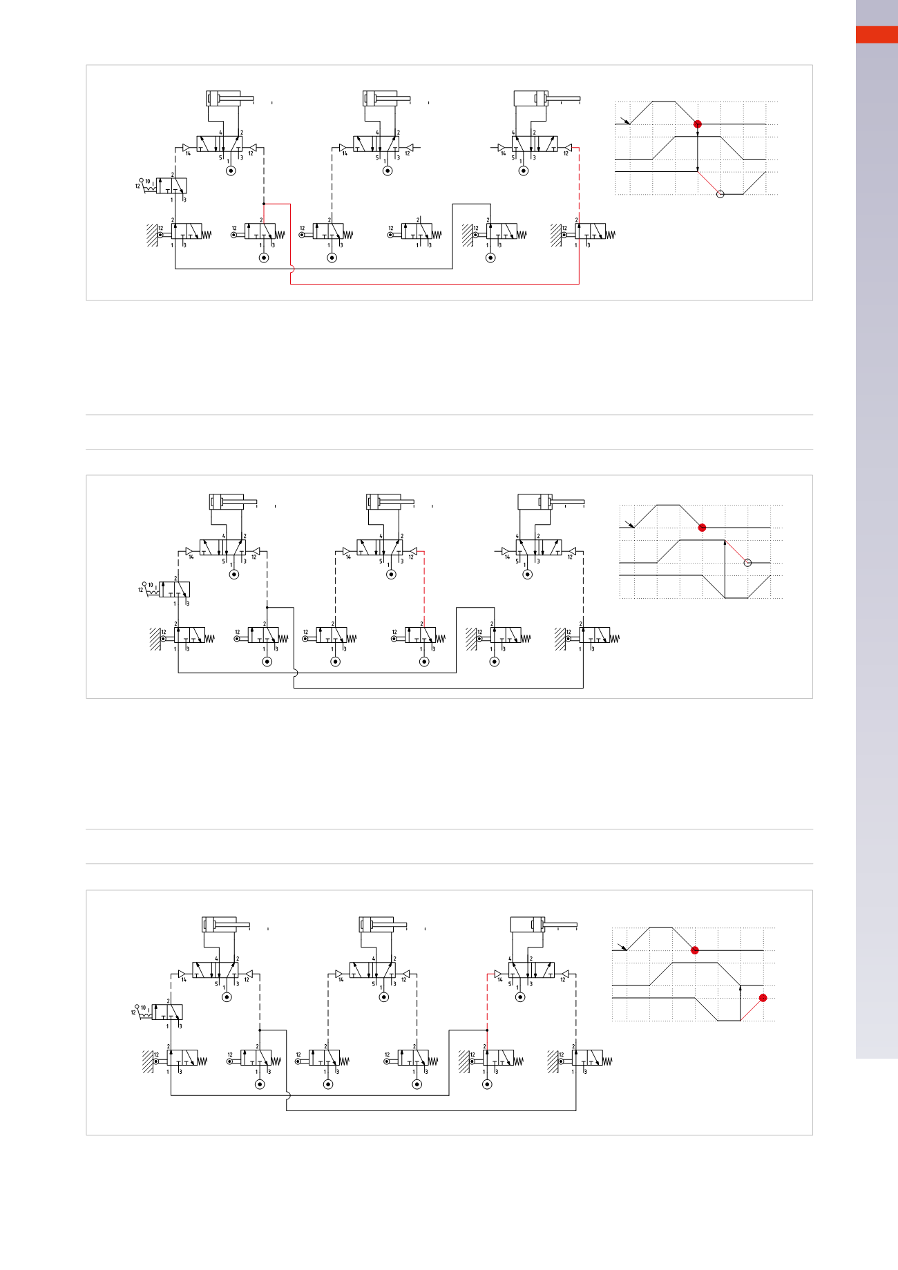
CIRCUIT TECHNIQUE
Figure 82
Phase 5
:
B –
The limit switch
c0
, which permits the negative stroke of the piston rod/piston of cylinder
B
, can be fed from the
compressed air network as the positive stroke only occurs in the following cycle.
B –
=
c0
A+=b0 * c1 * I.C.
B+=a1
A - = b1
C - =b1 * a0
B - = c0
B
C
+
-
A
+
-
+
-
b1
a0
c0
b0
c1
b1
a1
c0
b0
a0
a0 a1
b0 b1
c0 c1
A
B
C
I.C.
I.C.
5
1 2
a1
4
6 1
3
Fig. 82
A+=b0 * c1 * I.C.
B+=a1
A - = b1
C - =b1 * a0
B
C
+
-
A
+
-
+
-
b1
a0
c0
c1
b1
a1
b0
a0
a0 a1
b0 b1
c0 c1
A
B
C
I.C.
I.C.
5
1 2
4
6 1
a1
3
Fig. 81
Figure 83
Phase 6
:
C+
Upon termination of the negative stroke, the piston rod/piston of cylinder
B
actuates limit switch
b0
, which feeds
limit switch
c1
, and consequently the
I.C.
command and the pilot signal of the main valve of cylinder
C
for its
positive stroke.
C+
=
b0
A+=b0 * c1 * I.C.
B+=a1
A - = b1
C - =b1 * a0
B - = c0
C+=b0
B
C
+
-
A
+
-
+
-
b1
a0
c0
b0
c1
c1
b1
a1
c0
b0
a0
a0 a1
b0 b1
c0 c1
A
B
C
I.C.
I.C.
1 2
a1
4
6
1
3
5
Fig. 83
The sequence has finished and returns to the initial state: limit switches
b0
and
c1
are activated and their outputs
active as they are fed by the compressed air network. Limit switch
a0
is activated but not powered. The activation
of the
I.C.
command enables the sequence to restart.
5
177
CAMOZZI
>
CIRCUIT TECHNIQUE