


 181 / 218

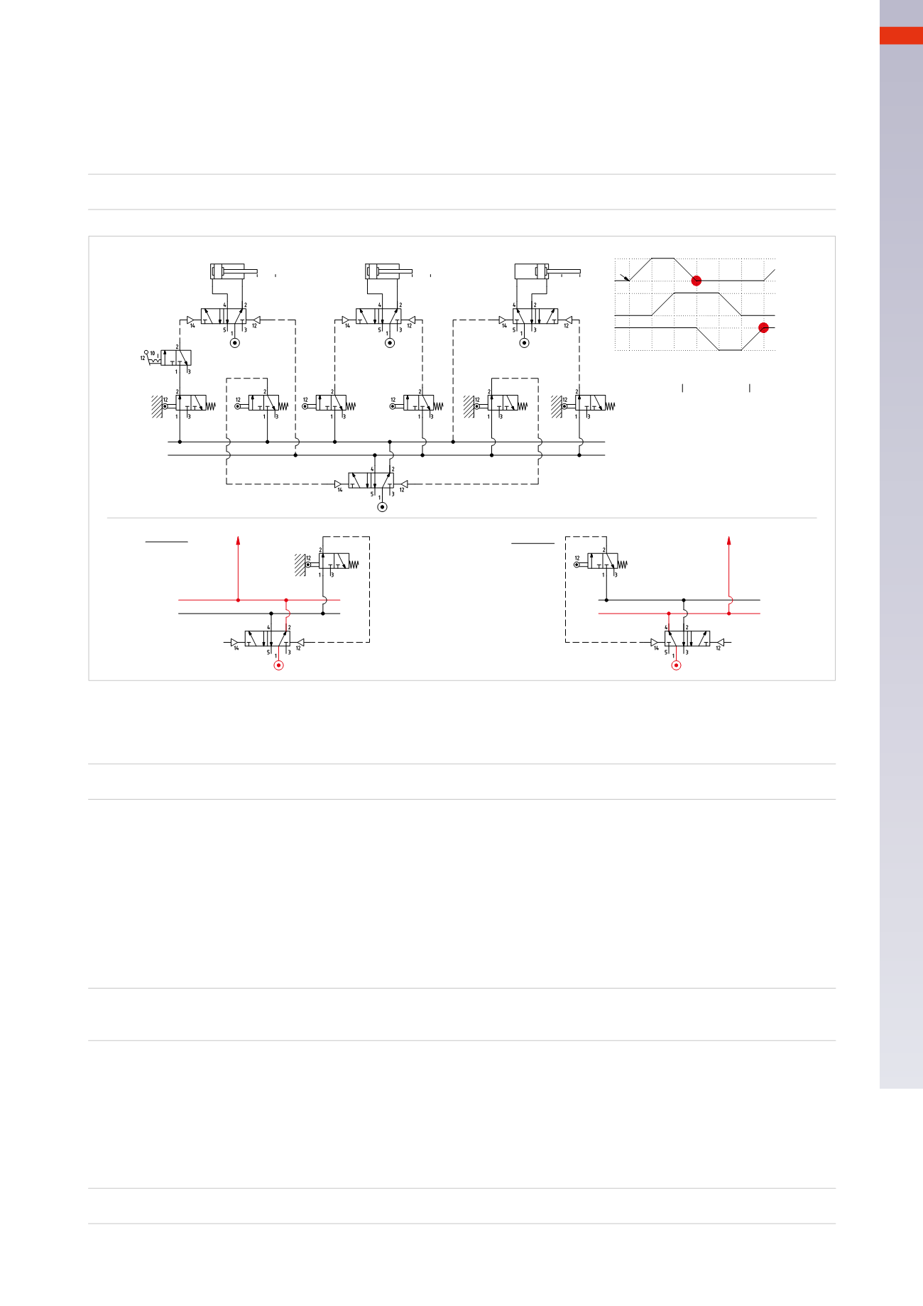
CIRCUIT TECHNIQUE
Memory techniques
We analyze a new sequence and detect the presence of blocking signals.
A – / B+ / B – / A+
Limit switch
a0
detects the negative stroke position of cylinder
A
and enables the positive stroke of the piston rod/
piston of cylinder
B
.
a0
is also presentwhen the piston rod/piston of cylinder
B
must complete thenegative stroke,
therefore
a0
is blocking.
Limit switch
b0
detects the negative end position of cylinder
B
and enables the positive stroke of the piston rod/
piston of cylinder
A
.
b0
is also present when the piston rod/piston of cylinder
A
must complete the negative
stroke, therefore
b0
is blocking.
We repeat the procedure described in the previous paragraph by dividing the sequence into groups.
A – / B+ / B – / A+
U1 /
U2
LineU1
provides power to the limit switches
a0
and
b1
.
Figure 85
Phase 1
:
A –
The last movement was that of the piston rod/piston of cylinder
A
which activated limit switch
a1
.
Its output changes over thememory valve, activating
LineU1
. The cycle start command
I.C.
is powered and its
activation permits the operation of the valve of cylinder
A
and the negative stroke of its piston rod/piston.
U1 * IC
=
A –
Phase 6
:
C+
Upon reaching limit switch
b0
, signal
S1
, poweredby the
U2Line
, is obtained,
S1
changes over thememory valve,
reactivating
U1
.
The output of limit switch
a0
, which previously blocked the valve of the cylinder
C
is no longer active, the
U1 Line
allows the piloting of themain valve of cylinder
C
and the positive stroke of its piston rod/piston.
U2 * b0
=
S1
=
U1
=
C+
U1
U1
b1
U2
U2
S2
A+ / B+ / A - / C - / B - / C
+
U1 * c1 * I.C. =A+
U1 * a1 =B+
U1 * b1=
S2
=
U2
=A-
U2 * a0 =C-
U2 * c0= =B-
U2 * b0=
S1
=
U1
=C+
U1
U1
U2
Phase 3
Phase6
B
C
+
-
5
A
1 2
a1
4
6
3
+
-
+
-
b1
a0
c0
c1
I.C.
b0
c1
b1
a1
c0
b0
a0
a0 a1
b0 b1
c0 c1
A
B
C
I.C.
U1
U2
U1
U2
S1
S2
b0
U1
U1
S1
C+
U2
U2
A -
Fig. 84
5
179
CAMOZZI
>
CIRCUIT TECHNIQUE