


 182 / 218

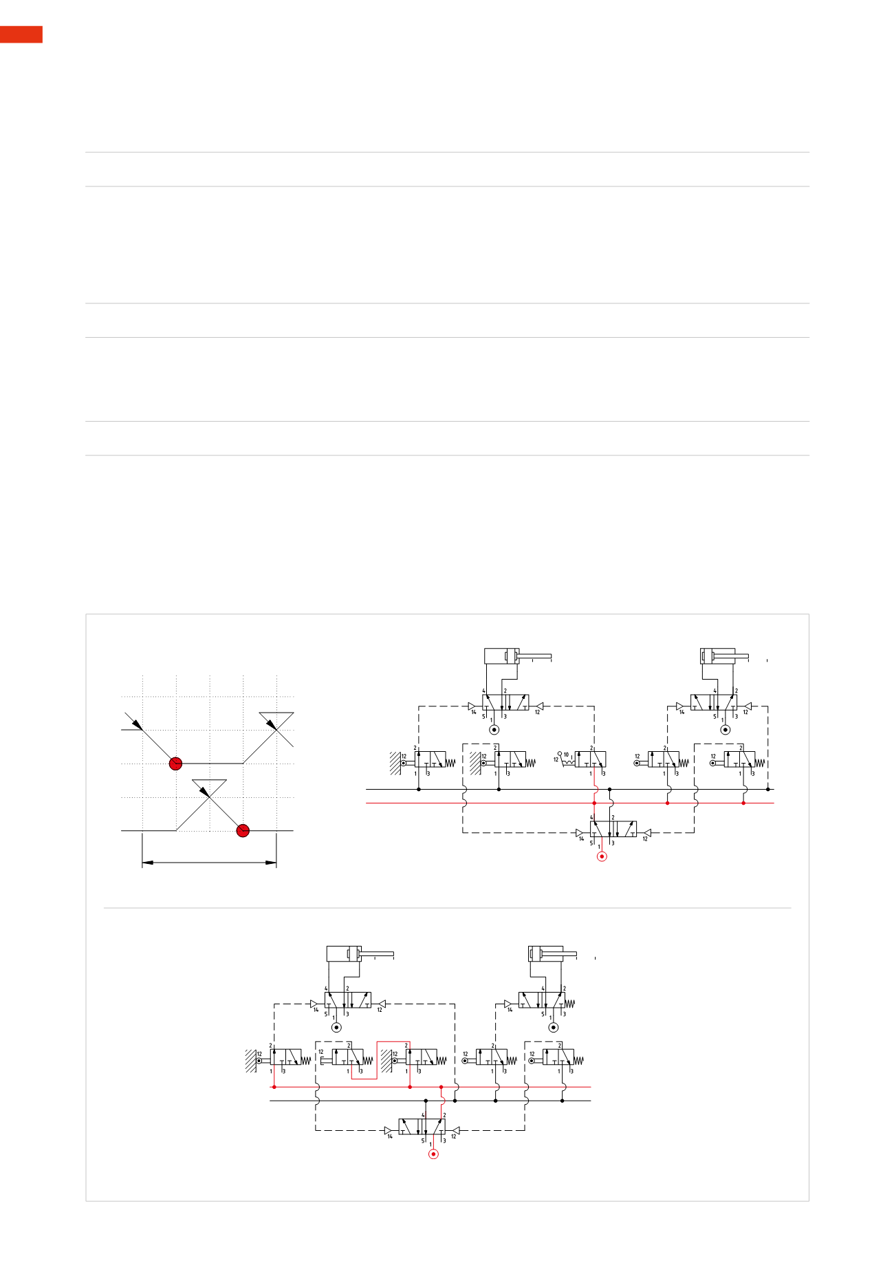
Figure 85
Phase 2
:
B+
Once thenegative endposition is reached, limit switch
a0
is activated, its output permits the operationof the valve
of cylinder
B
and the positive stroke of its piston rod/piston.
U1 * a0
=
B+
Phase 3
:
B –
Once the positive end position is reached, limit switch
b1
is activated, by dividing the sequence into groups, the
output of
b1
operating thememory valve enables
LineU2
and disables
LineU1
. By activating
LineU2
, limit swi-
tches
b0
and
a1
are powered.
Line U2
operates the valve of cylinder
B
which then executes the negative stroke
of its piston rod/piston.
U1 * b1
=
U2
=
B –
Phase 4
:
A+
Once thenegative endposition is reached, limit switch
b0
is activated, its output permits the operationof the valve
of cylinder
A
and the positive stroke.
U2 * b0
=
A+
Once the positive end position is reached, limit switch
a1
is activated. By dividing the sequence into groups, the
output of limit switch
a1
operating thememory valve enables
Line U1
and disables
Line U2
. By activating
Line
U1
limit switches
b1
and
a0
and the
I.C.
command are powered.
The non-blocking limit switches can be powered directly from the network, however should
b1
or
a0
be activated
accidentally, the piston rod/piston of cylinder
B
could provoke unwantedmovements. The
I.C.
command can be
positioned as indicated in either of the two circuits, the main valve of cylinder
B
can be either monostable or
bistable.
a0
A
B
-
+
-
ciclo
b0
b1
+
a1
I.C.
1
2
4 3
1
a0 a1
A
I.C.
b0 b1
B
U1
U2
U1
U2
a0
b1
b0
a1
a0 a1
A
b0 b1
B
U1
U2
U1
U2
a0
b1
b0
a1
Fig. 85
5
180
CAMOZZI
>
CIRCUIT TECHNIQUE