


 183 / 218

CIRCUIT TECHNIQUE
Techniquewithmemories in cascade
This is the simplest method and adaptable to any sequence.
With this technique, a relationship is establishedbetween the incoming signals from the limit switches (denotedby
the letter
S
followedby anumber indicating the sequence) and the output signals (denotedby the letter
U
followed
by the number of the signal that generated it).
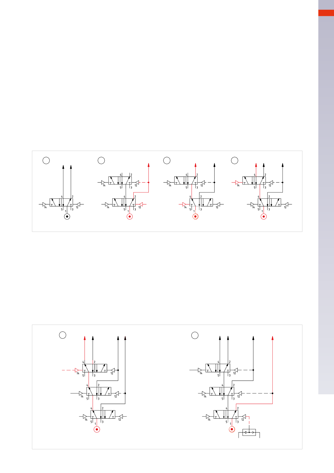
Figure 86
Pos. 1
: this is the situation observed in the previous paragraph where the sequence required two power lines
for the limit switches. The memory is a valve with double pneumatic command, fed by the main compressed
air network. When it receives pilot signal
S1
it activates
U1
, when it receives pilot signal
S2
it activates
U2
.
The presence of
U1
excludes the presence of
U2
and vice-versa.
Pos. 2
: if more than two lines are necessary, proceed as follows:
The first memory valve is fed by the compressed air network, the pilot signal
S1
activates
U1
which, in addition
to feeding the limit switch, allocates the position of the subsequent memory valve.
Pos. 3
: with the arrival of pilot signal
S2
, connected to the memory valve fed by the compressed air network, it
changes over, interrupting the output which enabled
LineU1
, it also activates the output that feeds the previously
positioned valve. The new output is line
U2
.
Pos. 4
: in the presence of the pilot signal
S3
,
LineU3
is activated, thus interrupting
U2
.
1
2
3
4
U1
U2
U1
U1
U1
U2
U2
U3
S1
S1
S1
S2
S2
S1
S2
S3
Fig. 86
Two connected memory valves can provide three power Lines and only one of these three can be active, should
additional Lines be neededmorememory valves are added.
Given a sequence and having identified the presence of blocking signals, the sequence is divided into groups, so
that the letters which identify the cylinders do not appear more than once in the same group, the number of
memory valves needed is equal to the number of groupsminus one.
Figure 87
Pos. 5
: with respect to Pos.4. a memory valve has been added to obtain
U4
. When signal
S4
is present,
U4
is
activated, interrupting
U3
.
Pos. 6
: with the removal of signal
S4
, and in the presence of signal
S1
the cascade is reset, reactivating
U1
.
When drawing a pneumatic circuit which includes this technique, an external reset system of the cascade should
be included to be used during the
Reset
phase after an emergency stop.
5
6
U2
U4 U3
U1
U2
U4
U3
U1
S4
S2
S1
Reset
S3
S2
S1
S3
S4
Fig. 87
5
181
CAMOZZI
>
CIRCUIT TECHNIQUE