


 184 / 218

Memories in cascade
We draw the pneumatic circuit of a hypothetical sequence, analyzing the movements of the cylinders Phase by
Phase. Aworkstation is required in order to perform the following operations:
Positioning of the component cylinder
A
Clamping the piece
cylinder
B
Drilling operation
cylinder
C
Boring operation
cylinder
D
The sequence to be realised is:
A+ / A – / B+ / C+ / C – / D+ / D – / B –
1
2
3
4
5
6
7
8
Required conditions:
The Start command is achieved by pressing the
I.C.
button, in this example the Emergency stop function is not
implemented. If theworkstation is inactive, the limit switches, even if activated, are also inactive.
Selection of main valves:
Analyzing the sequence, we observe that cylinders
C
and
D
reverse their direction through their respective positive
limit switches
c1
and
d1
. For these cylinders, themain valves can be
monostable
. For cylinder
A
this selection is
not possible as the operator acts with a short impulse signal for the Start, the valve in this case is
bistable
.
Cylinder
B
requires a
bistable
valve, as it remains at the respective end positions for more than one Phase.
Search for blocking signals, division into groups and calculation of the necessary number of memory valves:
We subdivide the sequence into groups ensuring the letters representing the cylinders do not appear more than
once in the same group, we identify the requiredmemory valves.
A+ / A – / B+/ C+ /
C – / D+ /
D – / B –
U1 /
U2
/
U3 /
U1
U1
feeds the limit switches in positions
a1
;
d0
;
b0
U2
feeds the limit switches in positions
a0
;
b1
;
c1
U3
feeds the limit switches in positions
c0
;
d1
The number of memory valves to use in order to realize a cascade are two (number of groupsminus 1).
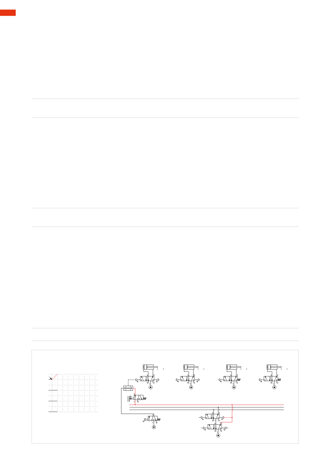
We represent the cylinders and their main valves, the twomemory valves connected in cascade, the limit switch
b0
, whichwas the last to be operated, and the
I.C.
valve.
Figure 88
Phase1
: adhering to thedivisionof thegroups,
U1
is activeand feeds limit switch
b0
. The start of the cycle requires
the presence of the
I.C.
command and
b0
, the output signals from these valves, via the
AND
function, operate the
main valve of cylinder
A
, which, by changing over, allows the piston rod/piston to complete positive stroke
A+
.
The
LineU1
prepares the subsequent memory valve, in addition to powering limit switch
b0
.
U1 * I.C. * b0
=
A+
+
+
-
D
+
-
C
+
-
B
-
A
I.C.
1
2 3 54 6
1 7 8
U1 * I.C. * b0 =A+
Cil. "A"
Cil. "B"
Cil. "C"
Cil. "D"
a0 a1
b0 b1
c0 c1
d0 d1
b0
I.C.
U1
U2
U3
U1
U2
U3
S1
Fig. 88
5
182
CAMOZZI
>
CIRCUIT TECHNIQUE