


 185 / 218

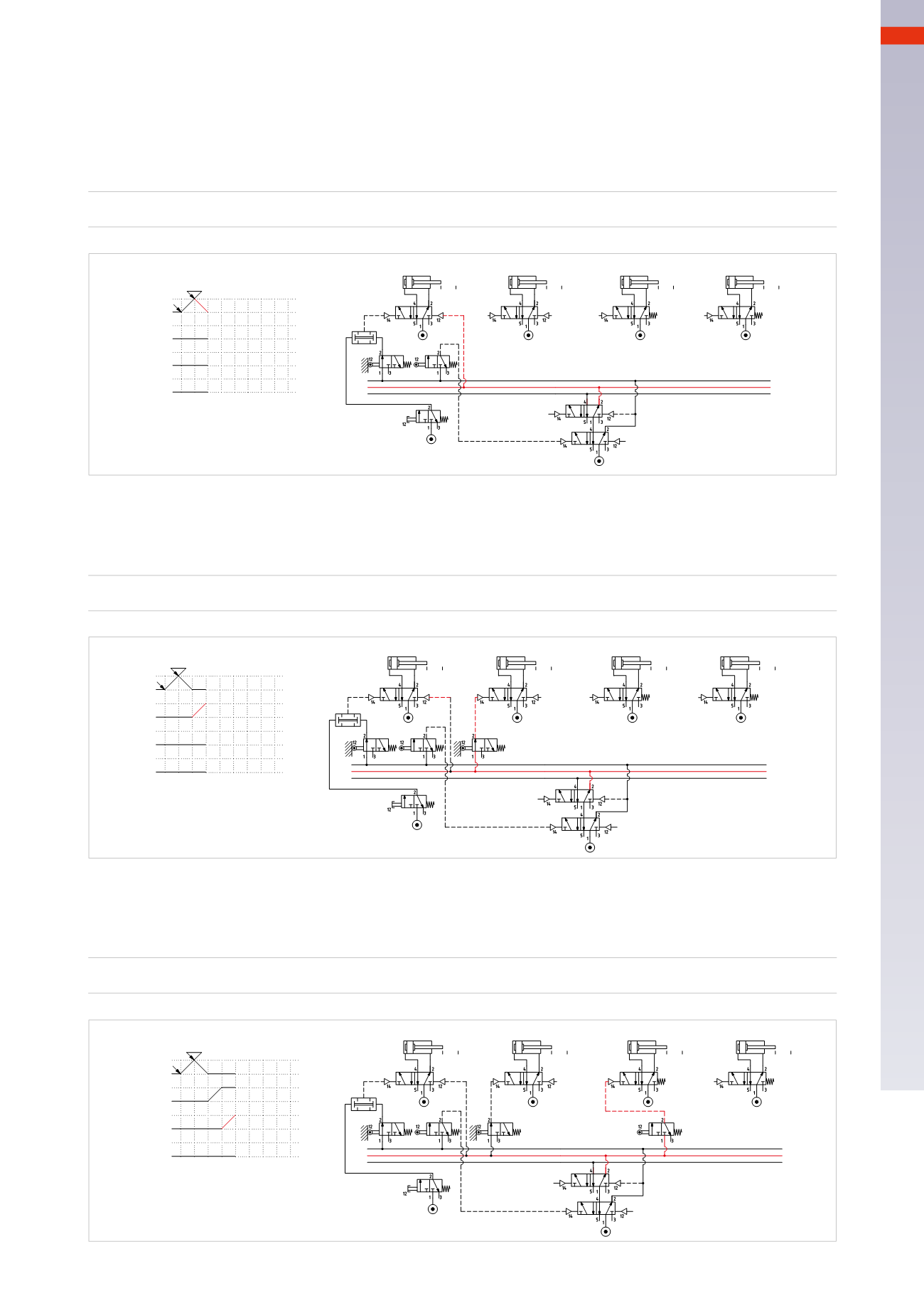
CIRCUIT TECHNIQUE
Figure 89
Phase 2
: once the piston rod/piston of cylinder
A
has reached the end position, it activates limit switch
a1
, which
is also fedby the
U1Line
, as it belongs to the same group, signal
S2
is generated, operating thememory valveand
changing its state. By changing over, thememory valve interrupts
Line U1
and activates
U2
.
Line U2
is directly
connected to pilot port 12 of themain valve of cylinder
A
to execute the negative stroke
A –
.
Activating the
I.C.
button does not result in anymovement, as
LineU1
is no longer active.
U1 * a1
=
S2
=
U2
=
A –
+
+
-
D
+
-
C
+
-
B
-
A
a1
U1 * I.C. * b0 =A+
U1 * a1=S2 =U2 =A-
I.C.
Cil. "A"
Cil. "B"
Cil. "C"
Cil. "D"
a0 a1
b0 b1
c0 c1
d0 d1
b0
a1
I.C.
U1
U2
U3
U1
U2
U3
S1
S2
1 3 54 6
1 7 8
2
Fig. 89
Figure 90
Phase3
: the piston rod/piston of cylinder
A
reaches andactivates limit switch
a0
,whose output operates themain
valve of cylinder
B
in order to execute the stroke
B+
.
U2 * a0 *
=
B+
+
+
-
D
+
-
C
+
-
B
-
A
I.C.
a1
U1 * I.C. * b0 =A+
U1 * a1=S2=U2 =A-
U2 * a0 =B+
a0
Cil. "A"
Cil. "B"
Cil. "C"
Cil. "D"
a0 a1
b0 b1
c0 c1
d0 d1
b0
a1
a0
I.C.
U1
U2
U3
U1
U2
U3
S1
S2
2
3
54 6
1 7 8
1
Fig. 90
Figure 91
Phase 4
: the piston rod/piston of cylinder
B
reached and activates limit switch
b1
, whose output operates the valve
of cylinder
C
in order to execute the stroke
C+
.
U2 * b1 *
=
C+
+
+
-
D
+
-
C
+
-
B
-
A
a1
U1 * I.C. * b0 =A+
U1 * a1=S2 = U2 =A-
U2 * a0 =B+
U2 * b1 =C+
b1
a0
I.C.
Cil. "A"
Cil. "B"
Cil. "C"
Cil. "D"
a0 a1
b0 b1
c0 c1
d0 d1
b0
a1
a0
b1
I.C.
U1
U2
U3
U1
U2
U3
S1
S2
2
5
4
6
1 7 8
1 3
Fig. 91
5
183
CAMOZZI
>
CIRCUIT TECHNIQUE