


 62 / 218

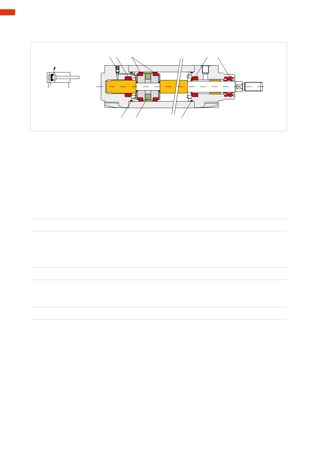
Figure 9
Double Acting Cylinders (D/A)
: can be with or without pneumatic adjustable end cushioning at the end of the stroke.
A C
C B
E D
D
F
MAGNETIC
CUSHIONED
DOUBLE-ACTING
CYLINDER
Fig. 9
Sizing of a cylinder according to the applied load
The Force created by a cylinder can be used in two ways:
Statically
: when the cylinder completes the stroke “under vacuum” and its Force must intervene onto a fixed
obstacle (load), for example the blocking of working pieces, bending operations etc…
The Force
F
required by each of these operations must correspond to the product of the pressure
p
, multiplied by
the piston surfaces:
F
=
p * S
Dynamically
: when the cylinder has to move a load, in this case the evaluation of the Force is made according to
the direction of the movement which can be:
Vertically
: Force
F
must overcome the resistance of the load;
F
=
m * g
Horizontally
: Force
F
must overcome the frictional resistance. Its value is equal to the product of the weight of the
body
F
multiplied by the friction coefficient “μ” of the support system (sledges, trolleys etc.).
F
=
Fp *
μ
At an equal load, horizontal movement requires less Force than vertical movement.
The performance of the pneumatic cylinders may be determined through appropriate adjustments.
The most common are:
Maximum speed
: the type of construction, the size of the connection pipes, the capacity of control valves, flow
controllers settings combine to determine the speed of the cylinder.
Kinetic energy
: is the energy acquired from the load during its movement and must be reduced before the piston
reaches the end of the stroke to avoid impact against the cylinder head. In order to reduce the magnitude of this
energy, some cylinders are equipped with adjustable cushioning devices, which reduce the speed towards the end
of the stroke.
To better understand what has been discussed and to understand the effectiveness of these braking systems,
observe the graph illustrating the value of the load to be cushioned on the
x-axis
and the piston speed on the
y-axis
.
This graph was obtained by means of experimental tests using:
• double-acting cylinders;
• load carrying trolley mounted on bearings and mobile on horizontal columns;
• electronic equipment for measuring time;
• test pressure
p
= 6
bar
.
3
60
CAMOZZI
>
CYLINDERS