The company reserves the right to vary models and dimensions without notice.
These products are designed for industrial applications and are not suitable for sale to the general public.
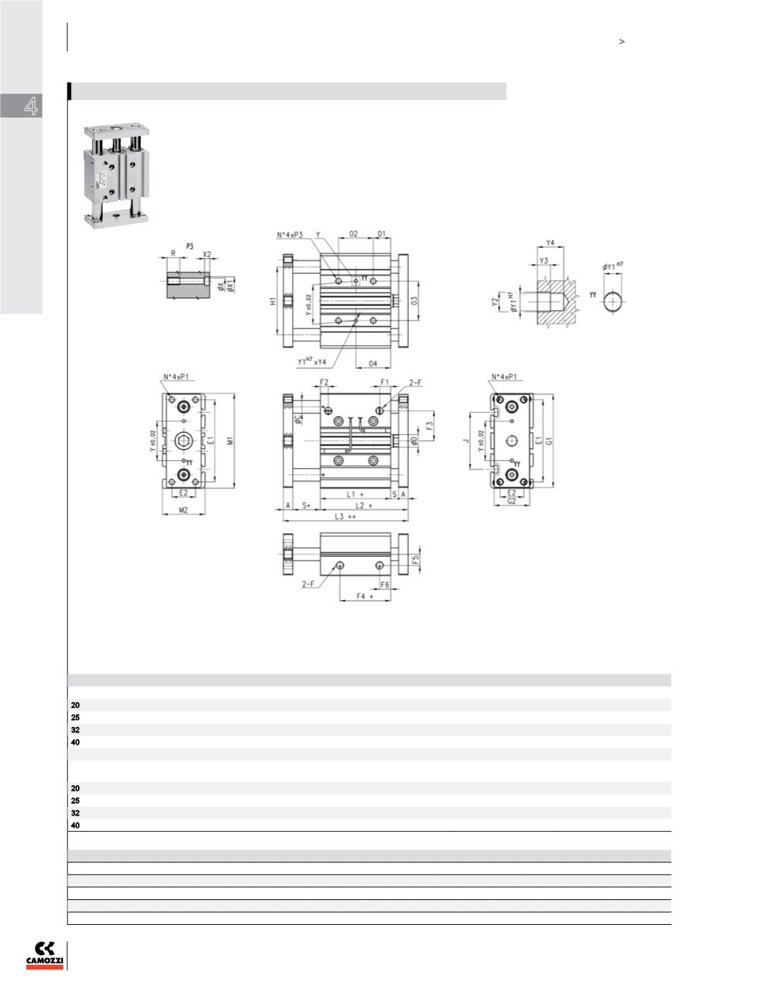
RODLESS AND GUIDED/TWIN-BORE CYLINDERS
Rodless and Guided/Twin-Bore Cylinders
4
NORTH AMERICAN CYLINDER & ACTUATOR CATALOG
>
Release 8.5
240
DIMENSIONS (mm)
Ø A ØD E1 E2 F F1 F2 F3 F4 F5 F6 G1 G2 H1 L1 L2 L3 M1 M2 01 03 R S Y
20
10 10 70 18 1/8 10,5 10,5 25 12,5 11,5 10,5 81 30 54 37 53 69 83 36 17 28 12 6 28
25
10 12 78 26 1/8 11,5 8 28,5 12,5 13,5 11,5 91 40 64 37,5 53,5 69,5 93 42 17 34 12 6 34
32
12 16 96 30 1/8 12,5 9.5 34
7
15 12,5 110 45 78 37,5 59,5 81,5 112 48 21 42 16 10 42
40
12 16 104 30 1/8 13 12 38 13 18 13 118 45 86 44 66 88 120 54 22 50 16 10 50
+ = add the stroke
++ = add the stroke 2 times
Note: for out of standard intermediate strokes (ex. stroke 35), you have to consider the dimensions referring to the immediately higher stroke (ex. stroke 40).
DIMENSIONS
Ø
P1
P3
Y1
Y2
Y3
Y4
X
X1
X2
J
K
20
M5x0,8
M6x1
3
3,5
3
6
5,5
9,5
5,5
44
M5
25
M6x1
M6x1
4
4,5
3
6
5,5
9,5
5,5
50
M5
32
M8x1,25
M8x1,25
4
4,5
3
6
6,5
11
7,5
63
M6
40
M8x1,25
M8x1,25
4
4,5
3
6
6,5
11
7,5
72
M6
02
stroke 20-30
02
stroke 40-100
02
stroke 125-200
04
stroke 20-30
04
stroke 40-100
04
stroke 125-200
QCBF
ØC
QCTF
ØC
20
24
44
120
29
39
77
10
12
25
24
44
120
29
39
77
12
16
32
24
48
124
33
45
83
16
20
40
24
48
124
34
46
84
16
20
Mod. QCTF and QCBF type “A”


