The company reserves the right to vary models and dimensions without notice.
These products are designed for industrial applications and are not suitable for sale to the general public.
RODLESS AND GUIDED/TWIN-BORE CYLINDERS
Rodless and Guided/Twin-Bore Cylinders
4
NORTH AMERICAN CYLINDER & ACTUATOR CATALOG
>
Release 8.5
246
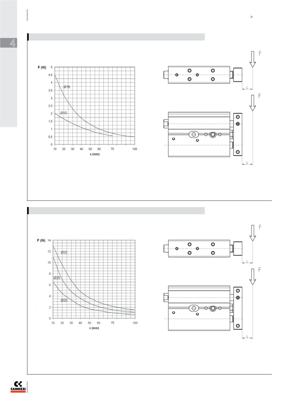
X = cylinder stroke mm.
F = load applied on the flange in N.
Load “ F “ should be considered fixed on the flange of the
cylinder and with a theorical projection of L = 0 mm.
X = cylinder stroke mm.
F = load applied on the flange in N.
Load “ F “ should be considered fixed on the flange of the
cylinder and with a theorical projection of L = 0 mm.
DIAGRAM MAX APPLICABLE LOADS DEPENDING ON THE STROKE ( X )
DIAGRAM MAX APPLICABLE LOADS DEPENDING ON THE STROKE ( X )


