


 148 / 218

1
2
_
+
2
_
+
_
+
1
3
5 4
1
3 2
A
B
C
A
B
C
cycle
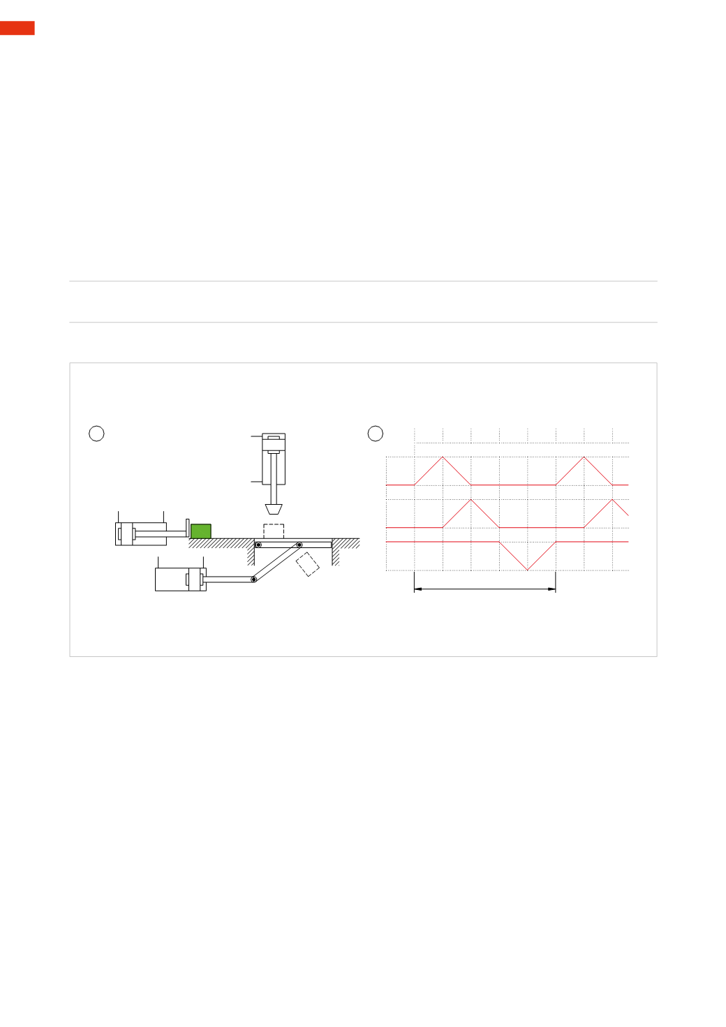
Fig. 26
Figure 26
Pos. 1
: to amanually positioned component, a holemust be punched and discharged into a container. Also in this
casewe observe the cylinders performing the operations in successive phases:
Phase 1
cylinder
A
positions the component under the hole puncher
A+
Phase 2
cylinder
A
clears theworking area
A –
cylinder
B
clears theworking area
B+
Phase 3
cylinder
B
returns directly after the punching operation
B –
Phase 4
cylinder
C
retracts to discharge the component
C –
Phase 5
cylinder
C
returns to position
C+
In this case, during Phase 2, we observe themovement of the piston rod/piston of both cylinders
A
and
B
.
This sequence can be expressed in the following literal form:
A+ / A – B+ / B – / C – / C+
1
2
3
4
5
Pos. 2
: graphical representation.
Signals generated by limit switches
Limit valves (or limit switches) are normally mechanically operated and are used to detect the movement of the
piston rod/piston in the cylinder or mechanical parts connected to them. The generated signal remains active
throughout the period of operation and confirms the attainment of a certain position. Each limit switch is normally
indicated by the lower case letter corresponding to the cylinder. The position is defined by a ZERO or ONE.
Cylinder
A
at negative end position, piston rod retracted
a0
Cylinder
A
at positive end position, piston rod extended
a1
Normally the output signals from the limit switches are used to permit the subsequent movements. On the flow
diagram it is important to indicate the position of each limit switch and the destination of the output signals
generated by them.
Figure 27
Cycle start
: the piston rod/piston of the cylinders are at the negative end position, their respectivemain valves
P
A
and
P
B
are positioned so that the outgoing compressed air feeds the negative chamber. This position is determined
by the last pilot signal received.
5
146
CAMOZZI
>
CIRCUIT TECHNIQUE