


 147 / 218

CIRCUIT TECHNIQUE
1
2
3
4
5
6
_
+
+
B
A_
_
_
+
+
_
_
B
2 1
+
B
+
_A
_
A_
+
+
B
2 1
3
+
B
+
A_
_
_A
+
+
1
2 1
3
2
1
cycle
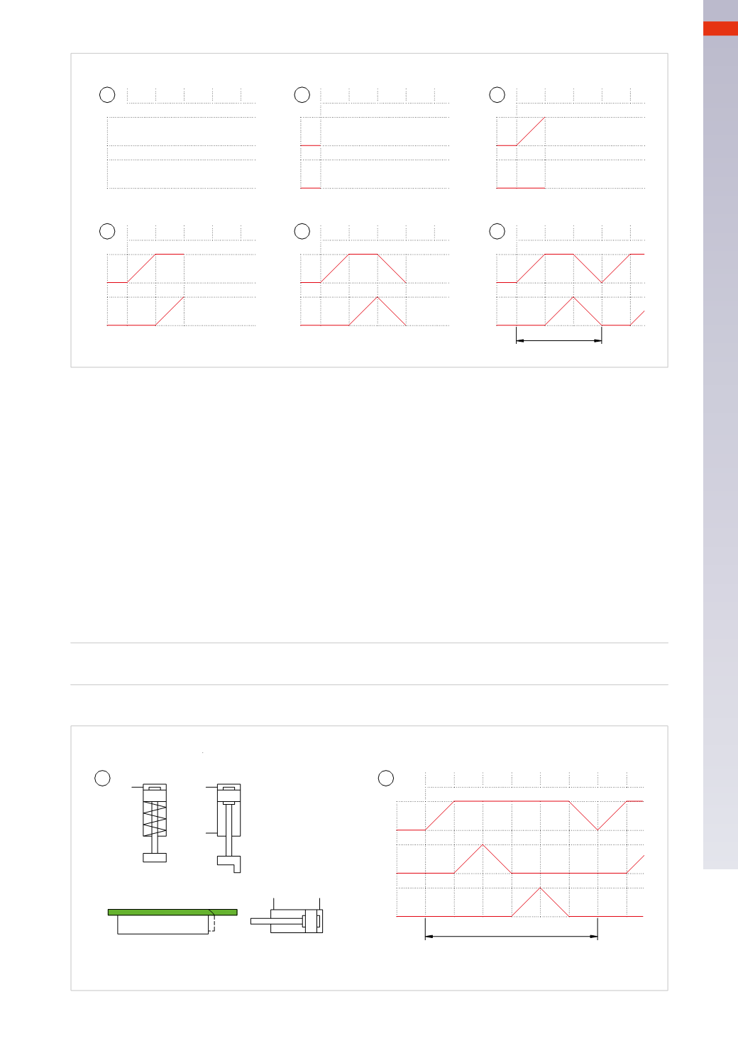
Fig. 24
Flow diagramwith various examples:
Figure 25
Pos. 1
: manually positionedmetal sheets are to be bent and have a hole punched on the short end. Devices with
cylinders that perform certain operations in successive phases are required:
Phase 1
cylinder
A
extends and clamps the sheet for thewhole duration of the operation
A+
Phase 2
cylinder
B
, if the component is blocked it can perform the bending operation
B+
Phase 3
cylinder
B
clears theworking area to allow the next movement
B –
Phase 4
cylinder
C
performs the hole punching
C+
Phase 5
cylinder
C
clears theworking area
C –
Phase 6
cylinder
A
releases the sheet which can now be removed
A –
In this case, no twomovements are simultaneous,
they are all sequential.
Representation of the sequence in literal form:
A+ / B+ / B – / C+ / C – / A –
1
2
3
4
5
6
Pos. 2
: graphical representation.
1
2
A
_
+
+
_
_
cycle
2
+
1
3
5 4
6 1 2
A
B
C
C
B
Fig. 25
5
145
CAMOZZI
>
CIRCUIT TECHNIQUE