


 64 / 218

1
A
B
C
2
3
Cushioning stroke
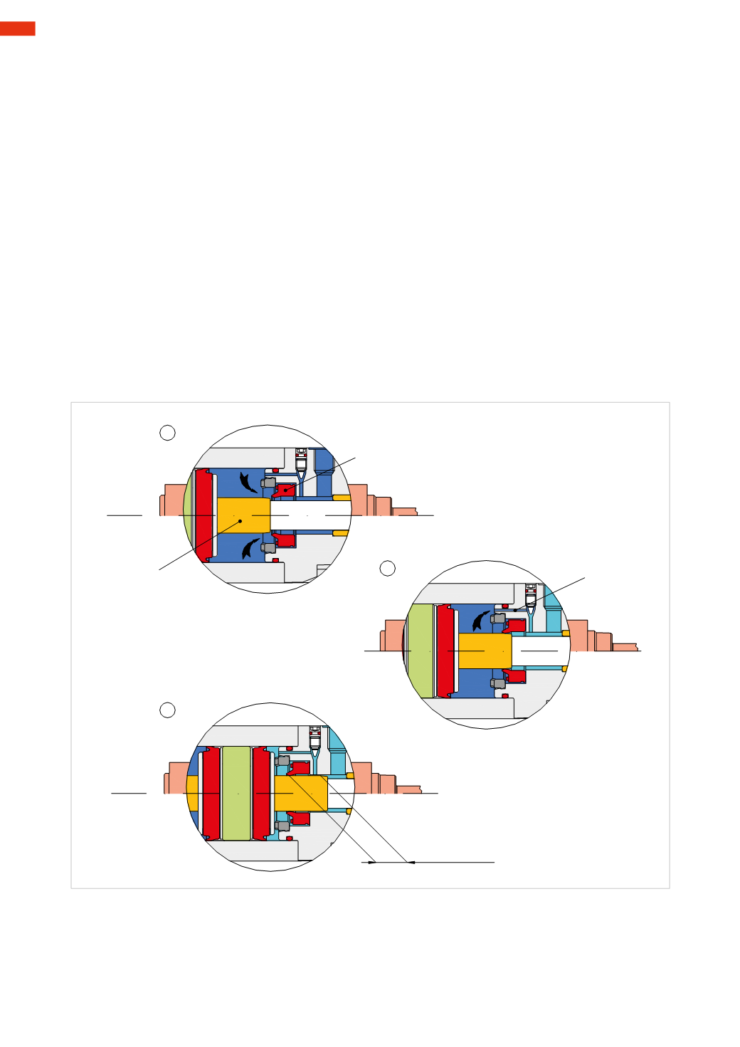
Fig. 11
Cushioning phase of themovement of a double-acting cylinder
Toavoiddamage to the structure of the cylinder or connectedmechanisms, the kinetic energy acquiredby the load
duringmovement should be reduced or cancelled before the piston reaches the end position.
Some cylinders are equipped with adjustable cushioning systems (shock absorbers) which, depending on the
diameter of the cylinder, act between 15 and 50
mm
of the final stretch of the stroke. This deceleration is
activated automatically and forces the discharged air to pass through an exhaust with a reduced section.
The rise in pressure in the exhaust chamber creates a greater resistance to movement of the piston rod/piston
with a consequent reduction of speed.
As illustrated in the previous diagram, there aremaximum energy levels that the cushioning systems can absorb,
the higher the load the lower the speed, the higher the speed the lower the load.
Using the front head of a cylinder as an example, we verify the operation of the cushioning system.
Figure 11
Pos. 1
: Cushioning seal
A
has no function.
The air is free tomove as the cushion sleeve
B
is not yet in contact with the inner rim of the seal
A
.
Pos. 2
: when the
B
is inserted into the rim of the seal
A
, it will bemoved axially in a specific position developing
two distinct sealing actions:
static
: through the flat surface supporting the cylinder head;
dynamic
: when the cushion sleeve is resting on the rim of the seal.
In this situation the quantity of compressed air present between the piston and cylinder head can only exhaust
through
C
. The space available for the braking operation is referred to as the “cushioning stroke”.
Pos. 3
: the piston has completed its stroke and the reduced pressure from the chamber can be exhausted into the
atmosphere.
The above also occurs in the rear head cylinder when the piston returns.
3
62
CAMOZZI
>
CYLINDERS