


 68 / 218

1
2
3
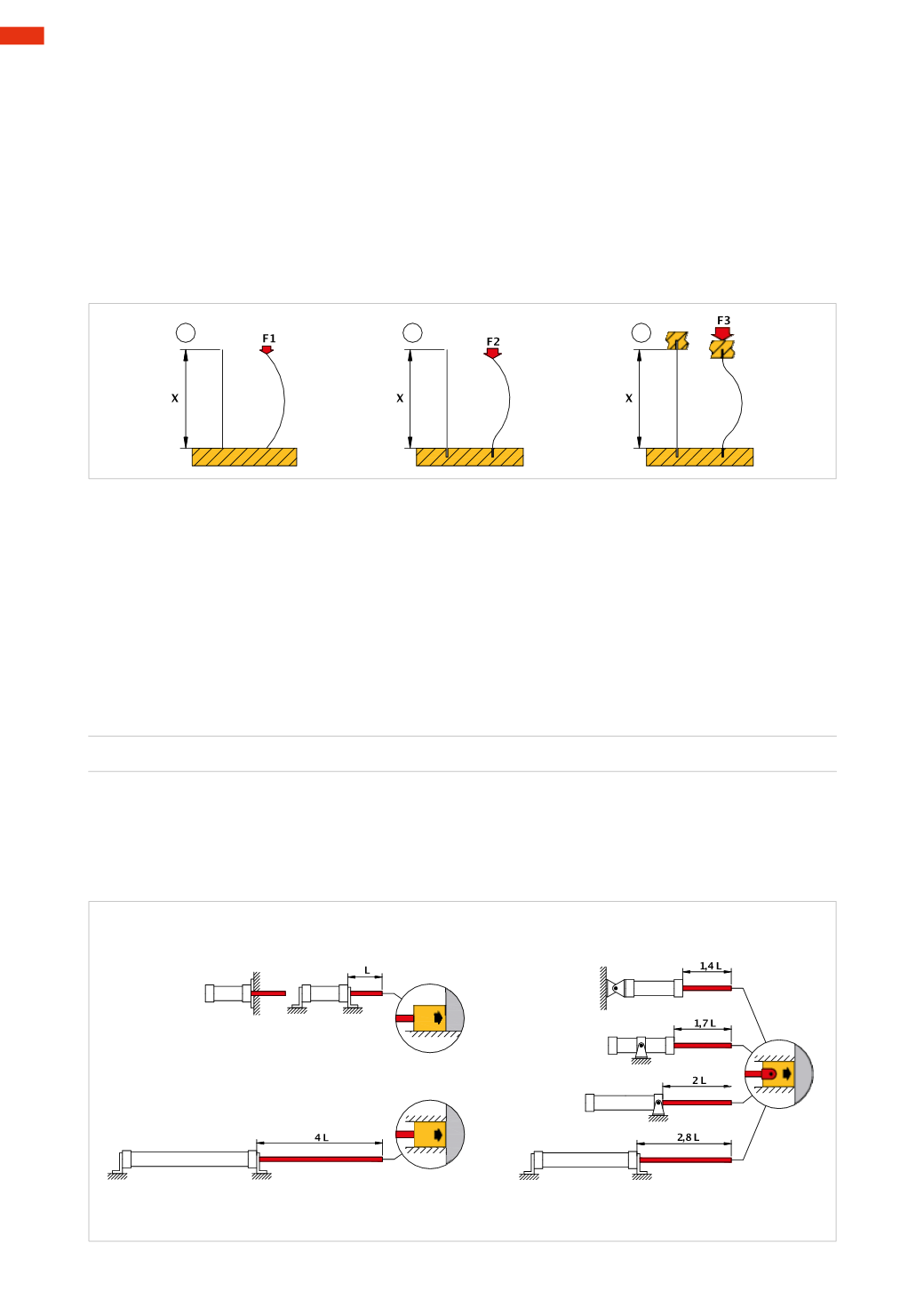
Fig. 16
Rod stress with a compression load
While progressively pressing the ends of a wooden match held between thumb and index finger, we notice that
it bends until it reaches breaking point; repeating the same procedure with one of the broken parts, if we are to
achieve the same result, we need to apply amuch greater force.
Figure 16
Pos. 1
: assume that, the match is represented by a rod of length
X
, and that under the action of a Force
F
1
the
rod bends.
Pos. 2
: if one end of the rod is constrained, in order to obtain flexing, a greater Force is necessary than in the
previous case
F
2
>
F
1
. The rod undergoes a bigger curvature and only in the non-guided part.
Pos. 3
: with both ends of the rod constrained, the Force
F
3
needed to flex the piece is even greater
F
3
>
F
2
.
The central part of the rod undergoes a curvature.
With this example we want to highlight the fact that a piston rod, when compressed along the axis by a Force,
tends to flex with the possibility of breakage. This stress composed of “pressure-flex” is defined as “compression
load” and occurs when the length of a rod exceeds its diameter by 10 times.
The cylinders, according to regulations, have standards regarding these combinations between the dimension of
the rod and its diameter. The choice of the cylinder, made according to the thrust Force F
s
to be developed and
the dimension of the piston rod, is a consequence of this ratio.
Examples of installation:
Figure 17
Pos. A
: the cylinder is rigidly fixed to the structure; the piston rod is fixed to an object moving on a surface.We
introduce amechanical stop to the load so that the cylinder does not reach the end of the stroke. The Force from
the piston and the retaining load compresses the piston rod. The value of this Force is:
F
=
p * S
Figure 17
Pos. B/1-B/2-B/3
: the piston rod end is hinged and the working end is guided, the cylinder is fixed in different
ways and in different positions.
Pos. C
: the rod attachment is identical to Pos. B. the cylinder body is rigidly fixed to the structure.
Pos. D
: the cylinder body is rigidly fixed to the structure; the rod is inserted in thework-piece, which is guided.
A
D
C
B/3
B/2
B/1
Fig. 17
3
66
CAMOZZI
>
CYLINDERS