


 66 / 218

Cylinder brackets
The cylinder is capable of transforming the energy of the compressed air intomechanical (kinetic) energy.
It is comprised of a static part called the “body” with the dynamic part i.e. the piston connected to the rod.
To enable thedrivingForce on the axis of the rod tobeutilized, thebody of the cylindermust be fixed toa structure
in an appropriateway.
The elements fixing the body to the structure are defined “brackets” andmay be
rigid
or
oscillating
. It is important
that the cylinder bracketsminimize the radial loads that can be applied to the cylinder.
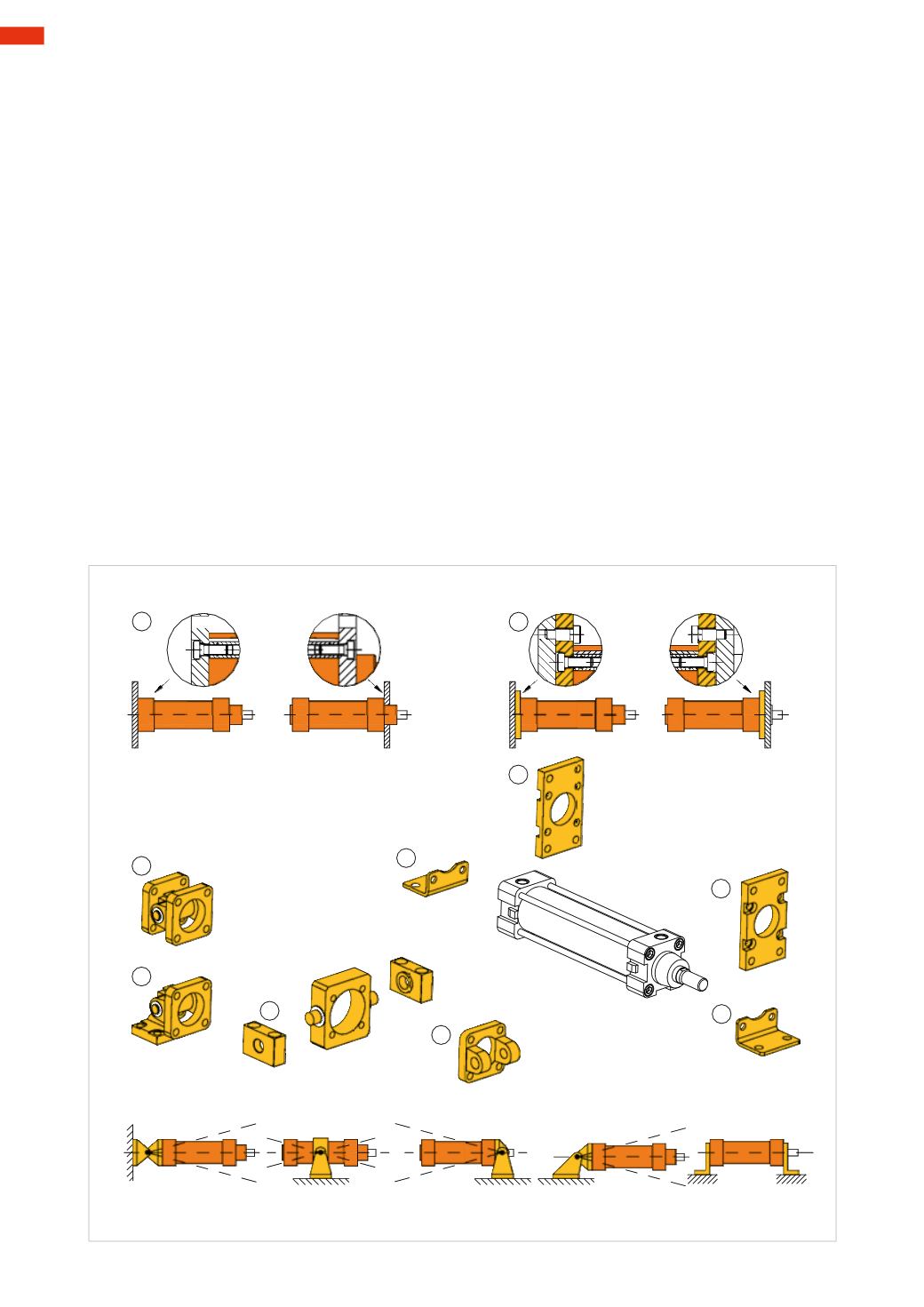
Examples of rigid cylinder brackets
:
Figure 13
Pos. A
:
Direct mounting
end caps are fixed directly to the equipment plate.
Pos. B
:
Flange
. This accessory allows perfect centering on the end caps. We do not recommend the use of the
flange on the rear head except in the case of short stroke cylinders or for installation in a vertical position. The
weight of the cylinder and of the piston rod, when outside, would weigh on the flange creating increasing flexion
as the length of the stroke increases.
Pos. C
:
Footmounting
. Fixed directly to the two end caps, they allow themounting of the cylinder on any surface,
provided it is parallel to the axis of the cylinder.
Examples of oscillating cylinder brackets
:
Figure 13
Pos. D
and
F
:
Rear trunnion
. This accessory can be supplied with the male trunnion. Their combination allows
both the oscillation and the fixing on the structure of themachine.
Pos. E
:
Front trunnion
. Owing to the presence of the rod, this is the only bracket possible for the front end cap.
The support of the trunnionmust be positioned on the structure of themachine.
Pos. G
:
Centre trunnion
. This is a type of oscillating cylinder bracket offering the possibility of being fixed on the
tube or on the cylinder profile at any point between two end caps.
C
C
E
G
F
D
A
B
B
B
Fig. 13
3
64
CAMOZZI
>
CYLINDERS