


 69 / 218

CYLINDERS
4
6
8
300 500
1000 2000
10
5000
10000
2
20000
200
500
1500
1000
30 50
100
200
500
1000 2000
B
A
Kg
N
Pressure inbar
LengthL inmm
Cil. Ø 200mm (40)
Cil. Ø 160mm (40)
Cil. Ø 125mm (32)
Cil. Ø 100mm (25)
Cil. Ø 80 mm (25)
Cil. Ø 63 mm (20)
Cil. Ø 50mm (20)
Cil. Ø 40mm (16)
Cil. Ø 32mm (12)
RodØ 40mm
RodØ 12mm
RodØ 16mm
RodØ 20mm
RodØ 25mm
RodØ 32mm
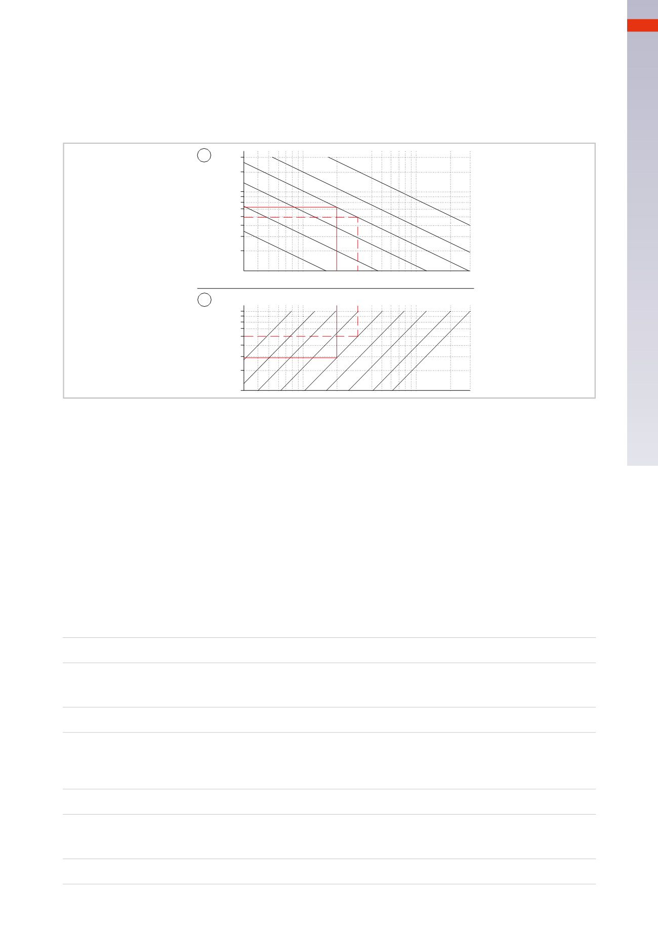
Example 1
: to find a cylinder that can exert a thrust Force
F
s
= 2000
N
, with a stroke
L
= 1400
mm
and a
pressure
p
= 6
bar
.
Figure 18
DiagramA
Starting from the value
F
s
=2000
N
various lines cross, the one representing a cylinder
D
=80
mm
with a25
mm
rod permits operation with the required pressure. Since the stroke of 1400
mm
is greater than
10 times the
diameter of the rod
(25
mm
in the example given), a compression load verification is required.
DiagramB
The selected cylinder, with
p
= 6
bar
, develops a Force
F
s
= 3000
N
(approx). To have a value
F
s
= 2000
N
it
is necessary to limit the pressure to 4
bar
.
From the value of 2000
N
, we follow the vertical line until it reaches the “rod Ø 25
mm
” line and this gives a
reading of maximum length
L
= 700
mm
(approx.).
Possible installation types
:
Figure 17
Pos. B/1
: is not possible, this installation type enables the cylinder to develop amaximum stroke length
L
max
=
700
mm *
1,4=
980
mm
Pos. B/2
: is not possible, this installation type enables the cylinder to develop amaximum stroke length
L
max
=
700
mm *
1,7=
1190
mm
Pos. B/3
: is at the limit so there is no margin of safety. This installation type enables the cylinder to develop a
maximum stroke length
L
max
=
700
mm *
2=
1400
mm
Pos. C
: this installation type is the only possible variant and offers a goodmargin of safety
L
max
=
700
mm *
2,8=
1960
mm
Verification of themaximum load:
Figure 18
Diagram A
: using the value of the Force
F
s
[N]
proportionate to the pressure
p
[bar]
, the diagram allows you to
choose the diameter of the cylinder alongwith the rod as indicated in parentheses.
Diagram B
: based on the Force
F
s
[kg]
and the length of the rod
L
[mm]
, the diagram shows the maximum
possible length for theworst-case connection, as indicated in Pos. A.
Fig. 18
3
67
CAMOZZI
>
CYLINDERS