


 67 / 218

CYLINDERS
Piston rodmountings
The connection of the cylinder body and the connection of the piston rodwhenmounted on the object to be driven
must be done in such way that anymisalignment between the axis of the piston rod, body and the driven object
is eliminated. Before putting an installation into operation, it is advisable to check the alignment of the loadwith
the piston rod from its retracted to extended position. An incorrect alignment will generate a radial Force on the
piston rodwhich eventuallywill cause deformation of the guide bushwhich consequently leads to prematurewear
of the tightening seals on the piston rod and piston.
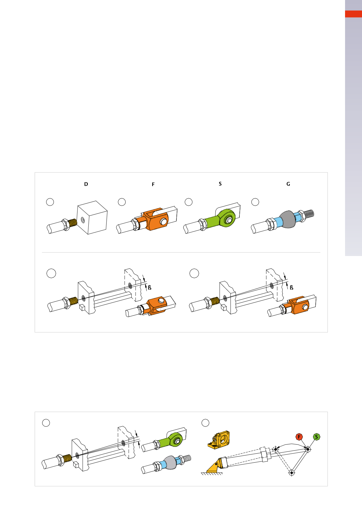
Figure 14
Pos. 1
: the object tobemoved is not bound toany guides and the rod canbedirectly secured to themoving object.
This fixture is defined as
direct
.
Pos. 2
: fastening by means of a
rod fork
. Provides liberty of movement in one axis, hence does not provoke any
radial Force due to themotion of the attached object in that axis.
Pos. 2a
: the moving load travels along an axis parallel to the cylinder centre line with a lateral deviation in the
horizontal plane of angle
β
. In this situation the rod exerts a radial load on the guide bush, by inserting a rod fork
you compensate for that angle and substantially reduce the radial load.
Pos. 2b
: the loadmovesupwards of angle
β
and the piston rod is forced towork on the upper part of bushing: also
in this case the fork, with a different orientation, is able to compensate themisalignment.
Pos. 3
: securedwith
swivel ball joint
.
Pos. 4
: fastening bymeans of a
piston rod socket joint
.
1
2
3
4
2b
2a
Direct
Rod clevis
Swivel ball joint
Piston rod
socket joint
Fig. 14
Figure 15
Pos. 5
: if the misalignment occurs in the two planes, the bush will be subject to wear in these two planes.
By inserting a swivel ball joint
S
or a piston rod socket joint
G
it is possible to compensate for that misalignment.
Pos. 6
: the angularmovement is always occurring on the same plane.With this assumption, andwith the evident
need to support the cylinder with a bracket that allows the cylinder to oscillate, the piston rod can be connected
to the lever with a rod fork
F
. If there’s any doubt about themovement remaining on the same plane, a swivel ball
joint
S
should be used instead. With this solution it is advisable to check the radial load generated by the weight
of the cylinder. When the rod is in external position this load is acting on the bronze bushing, provoking damage.
In particular, with long strokes it is preferable to use a cylinder mountingwith a center trunnion.
5
6
Fig. 15
3
65
CAMOZZI
>
CYLINDERS