


 146 / 218

Literal and graphical representation of themovement of cylinders
The cycle of a cylinder is themovement of the piston rod/piston in both directions. The positive (+) and negative
(-) strokes of the piston can be shown in two different forms:
Literal
: this formuses the identifying letter of cylinder and the direction of the piston stroke E.g.
A+ /A-
or
B- /B+
.
The slashed line indicates there are two separate phaseswith one pistonmovement in eachPhase.
Graphical
: all the letters are transcribed on lines. The phases of the cycle are indicated within the columns. The
type of action of the cylinder relevant to the Phase is illustrated in the square formed by the intersection between
the row and column. The number of the phase is indicated in the upper part of the diagram.
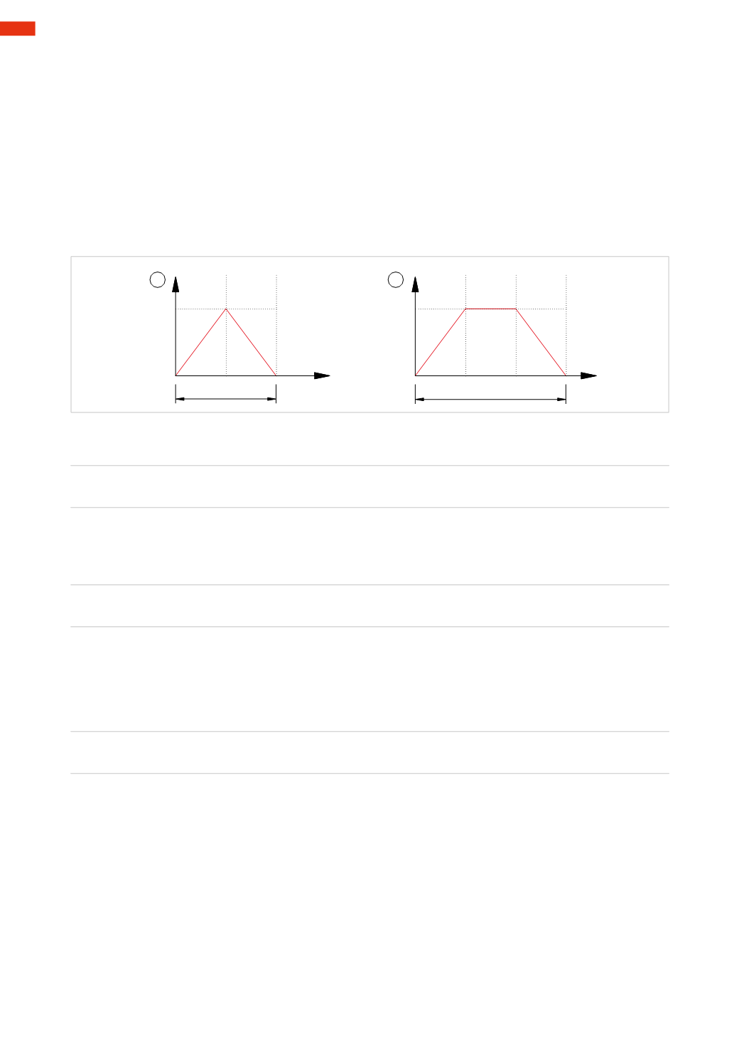
Figure 23
Pos. 1
: the cycle of the cylinder
A
(
A+
/
A –
) takes place in two Phases. Phase
A –
is the start position.
Pos.2
: thecycleof thecylinder
B
(
B+
/
B–
) takesplace in threePhases. In thiscasePhase
B–
isnot thestartposition.
cycle
cycle
+
A
_
+
B
_
2
1
2
1
3
1
2
Fig. 23
Whenmore than one cylinder is present in the same circuit, the following literal representation applies:
A+B+ / A – B –
1
2
The cycle operates in two Phases:
• in the first we have the
A+
and
B+
movements simultaneously,
• in the second
A –
and
B –
simultaneously.
A+ / B+ / A – B –
1 2
3
The cycle operates in three Phases:
• in the first
A+
,
• in the second
B+
,
• in the third
A –
and
B –
simultaneously.
Graphical representation of multiple cylinders
, we examine the following cycle as an example.
A+ / B+ / A – B –
1 2
3
Figure 24
Pos. 1
: preparation of the flow diagram, insert the same amount of rows as cylinders.
Pos. 2
: the first step involves inserting the names of the cylinders in the rows and illustrating the position they
assume at the beginning of the cycle.
Pos.3
: themovement of thecylinders is represented “stepby step”.Anoblique line is traced inside the relevant section,
starting from the initial position, to the target position.Where the cylinder remains unchanged over the course of the
stroke, the line indicating the phases inwhich there is nomovement is extended horizontally. In this Phase cylinder
A
must reach positive end position
A+
, the cylinder
B
does notmove, therefore the horizontal line is extended.
Pos. 4
: in the second Phase the cylinder
B
must reach the positive end position
B+
, we proceed in a similar way
as in the previous case, tracing an oblique line within the cell formed by the intersection of the line of cylinder
B
with Phase 2. In this same Phase, but with reference to cylinder
A
, the line is extended, as the cylinder remains
stationary.
Pos. 5
: in the third phase both cylindersmust return to the negative end position,
A – B –
.
Pos. 6
: the cycle is complete, and we resume with Phase one. The length of the cycle is indicated in the lower
part of the flow diagram.
5
144
CAMOZZI
>
CIRCUIT TECHNIQUE