NORTH AMERICAN CYLINDER & ACTUATOR CATALOG
>
Release 8.5
The company reserves the right to vary models and dimensions without notice.
These products are designed for industrial applications and are not suitable for sale to the general public.
ISO / VDMA CYLINDERS
ISO / VDMA Cylinders
1
59
6512
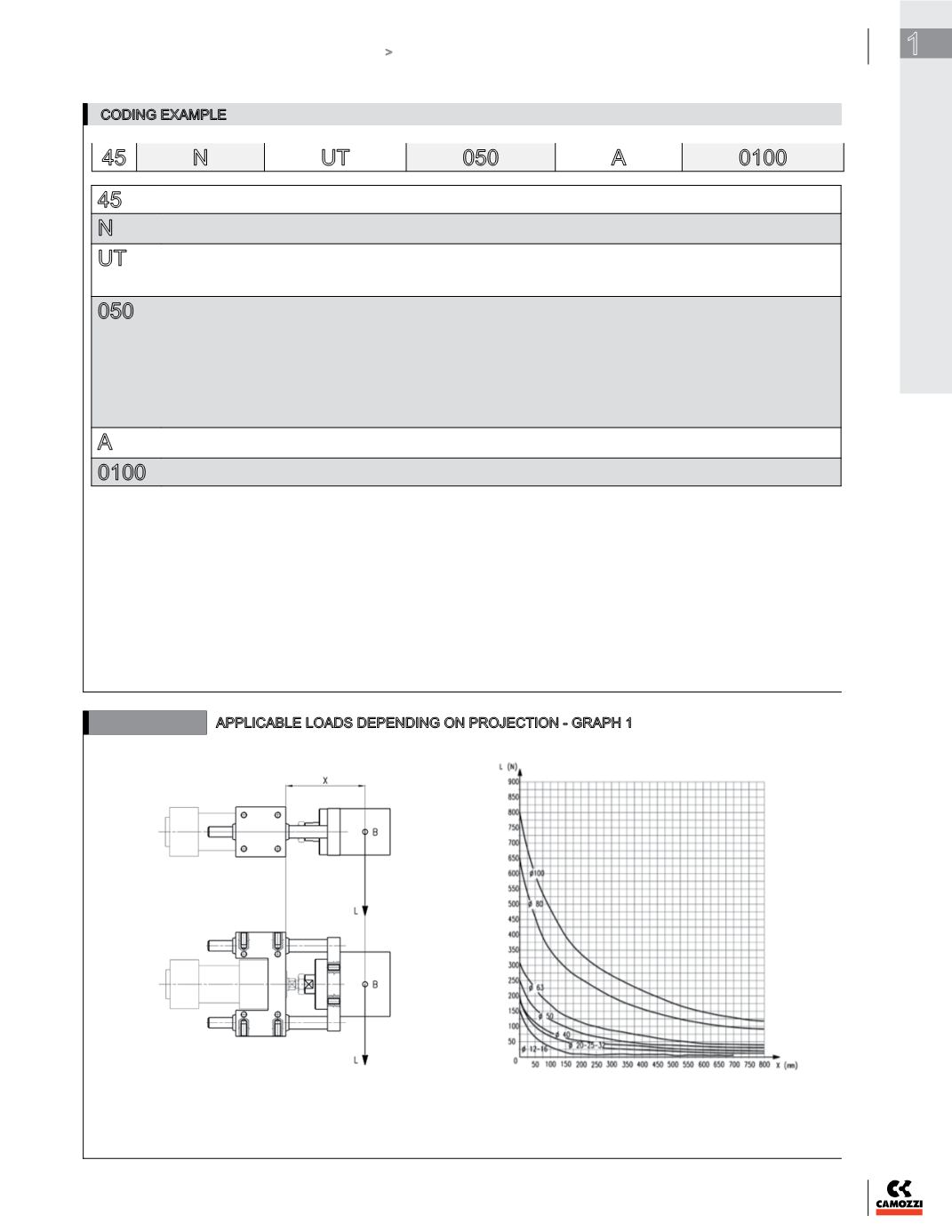
APPLICABLE LOADS DEPENDING ON PROJECTION - GRAPH 1
B = centre of gravity for applied load
L = load
X = fixed projection + stroke
fixed projection = distance to the centre of gravity
Guide “U” bushing support (45NUT)
CODING EXAMPLE
45
N
UT
050
A
0100
45
SERIES
N
VERSION
N = standard
UT
OPERATION
UT = “U” oil impregnated bronze bushing
HT = “H” oil impregnated bronze bushing
HB = “H” ball-bearing support guides
050
BORE
012
= 12 mm
016
= 16 mm
020
= 20 mm
025
= 25 mm
032
= 32 mm
040
= 40 mm
050
= 50 mm
063
= 63 mm
080
= 80 mm
100
= 100 mm
A
MATERIALS
A = anodized aluminium body, stainless steel columns AISI 420B for 45UT and 45HT, hardened carbon-steel columns C50 for 45HB
0100
STROKE in mm


