NORTH AMERICAN CYLINDER & ACTUATOR CATALOG
>
Release 8.5
The company reserves the right to vary models and dimensions without notice.
These products are designed for industrial applications and are not suitable for sale to the general public.
ISO / VDMA CYLINDERS
ISO / VDMA Cylinders
1
63
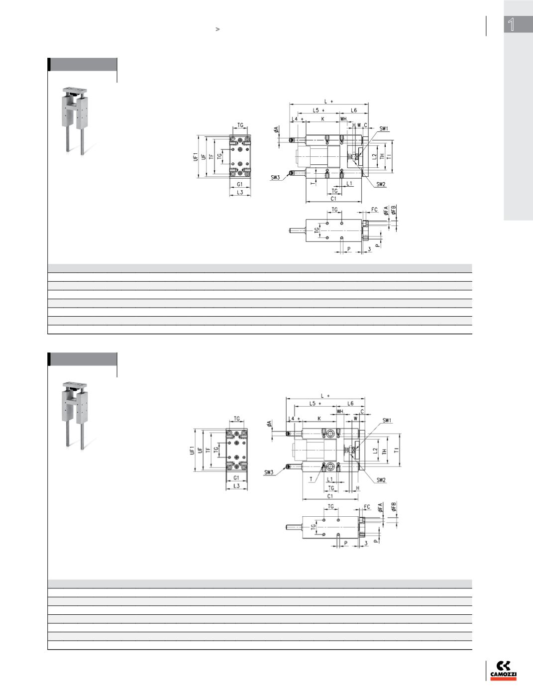
Guides Mod. 45NHT
Suitable for cylinders Series 60 and 61DIN/ISO 6431, ø 32, 40, 50, 63, 80 and 100.
These guides do not need lubrication. For applicable loads, see graph No. 3.
DIMENSIONS (mm)
Ø TF TG TH TI
UF G1 UF1 ØA WH C1 H W C K L L1 L2 L3 L4 L5 L6 P T ØFA ØFB FC SW1 SW2 SW3
32
78 32,5 61 74 90 45 97 12 17 125 6 17 12 76 177 4,3 50,2 50 37 94 64
M6 14 6,5 11 6,8 13 17 6
40
84 38 69 87 110 54 115 16 21 140 7 22 12 81 192 11 58,2 58 37 105 74
M6 14 6,5 11 6,8 15 19 6
50
100 46,5 85 104 130 63 137 20 26 149 8 26 15 78,5 205 19,8 70,2 70 37,5 106 89
M8 16 9 15 9 22 24 6
63
105 56,5 100 119 145 80 152 20 26 182 8 26 15 111 237 15,3 85,2 85 37 121 89
M8 16 9 15 9 22 24 6
80
130 72 130 148 180 100 189 25 32 215 9 32 20 128 280 21 105,4 105 42 128 110
M10 20 11 18 11 27 30 6
100
150 89 150 172 200 120 213 25 32 220 9 32 20 128 280 24,5 130,4 130 37 138 115
M10 20 11 18 11 27 30 6
Supplied with:
4
x fixing screws.
Draw note:
+ = add the stroke
Guides Mod. 45NHB
Suitable for cylinders Series 60 and 61 DIN/ISO 6431, ø 32, 40, 50, 63, 80 and 100.
To lubricate these guides, use the special lubricator. For applicable loads, see graph No. 2.
DIMENSIONS (mm)
Ø TF TG TH TI
UF G1 UF1 ØA WH C1 H W C K L L1 L2 L3 L4 L5 L6 P T ØFA ØFB FC SW1 SW2 SW3
32
78 32,5 61 74 90 45 97 12 17 125 6 17 12 76 177 4,3 50,2 50 37 94 64
M6 14 6,5 11 6,8 13 17 6
40
84 38 69 87 110 54 115 16 21 140 7 22 12 81 192 11 58,2 58 37 105 74
M6 14 6,5 11 6,8 15 19 6
50
100 46,5 85 104 130 63 137 20 26 149 8 26 15 78,5 237 19,8 70,2 70 69,5 106 89
M8 16 9 15 9 22 24 6
63
105 56,5 100 119 145 80 152 20 26 182 8 26 15 111 237 15,3 85,2 85 37 121 89
M8 16 9 15 9 22 24 6
80
130 72 130 148 180 100 189 25 34 215 9 32 20 128 280 21 105,4 105 42 128 110
M10 20 11 18 11 27 30 6
100
150 89 150 172 200 120 213 25 39 220 9 32 20 128 280 24,5 130,4 130 37 138 115
M10 20 11 18 11 27 30 6
Supplied with:
4
x fixing screws.
Draw note:
+ = add the stroke


